Purpose and contraindications for radiography
Thanks to the x-ray, you can make an accurate diagnosis and detect the presence or absence of pathological processes due to inflammation of the sinuses or injuries to the facial part of the skull. But it is not so easy to perform such an x-ray, since due to the complex structure of the bones of the skull and the large number of cavities in them, false shadows appear that can be misleading. Therefore, radiography of the paranasal sinuses is a very responsible procedure that should only be performed by an experienced and well-trained specialist. It is performed in any medical institution where there is an X-ray machine.
The otolaryngologist directs the patient to undergo this procedure in the following cases:
- severe pain in the cheekbones and nose, intensifying when the head is tilted forward;
- nosebleeds of unknown origin;
- the appearance of low-grade fever or sudden changes in body temperature;
- chronic runny nose, accompanied by severe nasal congestion, mucopurulent discharge and soreness;
- swelling and discoloration of the skin over the frontal and maxillary sinuses;
- in some cases, a skull scan is re-ordered by the doctor to assess the quality of treatment.
If the runny nose has become chronic, and the medications prescribed by the doctor have very little effect or do not help at all, then we can assume the development of inflammation of the maxillary sinuses . In this case, pain appears on the sides of the nose, intensifying with sudden movements, bending, or playing sports.
X-ray of the paranasal sinuses (PSN) also has contraindications. This procedure is prohibited for pregnant women and children under 7 years of age. Although this examination is considered harmless and is characterized by low levels of radiation exposure, it cannot be performed on expectant mothers due to the strong sensitivity of the fetus to this process. X-rays during pregnancy can cause birth defects in the child. This procedure is very rarely prescribed for preschoolers, since gamma rays negatively affect the growth of the child’s bones.
Expansion of the line of fuse links of the PPN TM TEXENERGO series
We bring to your attention PPN-41 fuse-links for currents from 400 to 1600A in the following versions: bolt-on (size 4)
straight knives (size 4A)
Fuse links of the PPN series are used to protect electrical equipment of industrial installations and electrical networks of three-phase alternating current with a rated voltage of up to 690V, frequency 50 and 60Hz, and direct current with a rated voltage of up to 440V inclusive, during overloads and short circuits.
Areas of application for fuse PPN (PPN 33, PPN 35, PPN 37, PPN 39, PPN41): ASU of residential, public and industrial buildings, transformer substations, control cabinets. The fuses comply with the requirements of GOST 31196.2.1 and GOST R IEC 60269-1.
Design Features:
- The fuse is designed with a trip indicator, which helps determine the condition of the fuse.
- The current-carrying elements of fuse links are made of electrical copper grade M1. PPN fuses comply with the standards GOST R 50339.0-2003 (IEC 60269-2-1-98) and GOST R 50339.2-92 (IEC 269-2-1-87).
- The contacts of the fuse and the PPN holder are made of electrical copper with galvanic coating with a tin-bismuth alloy, which prevents their oxidation during operation.
- The base (insulator) of the PPN (fusible insert) is made of reinforced thermosetting plastic, resistant to corrosion, mechanical stress, temperature changes and dynamic shocks that occur during short circuits up to 120 kA.
- The technology of filling fuses with filler in the form of highly purified quartz sand makes it possible to achieve a high filling density, which ensures effective extinguishing of the electric arc inside the fuse when it is triggered.
- Each holder of the PPN series is equipped with high-strength bolts and nuts of strength class 8.8. (GOST 1759.4-87 (ISO 898/1-78)
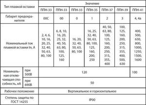
Specifications

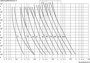
Time-current characteristics

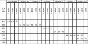
Maximum power loss of fuses

All products have been certified by reputable international laboratories and testing centers:
To quickly and easily place orders, use our service for selecting products based on references and article numbers.
You must register.
Contact our sales managers to find out about all current promotions and discounts (ext. 1200)
Preparing for the PPN procedure
Modern radiography of the paranasal sinuses is very informative and can provide a large amount of useful information about the state of human health, as well as about the structure of the facial part of the skull. If the frontal and maxillary sinuses are healthy, then they are filled with air and are completely permeable to X-ray rays.
The presence of inflammation in them leads to swelling of the mucous membrane and an increase in their thickness, which can be detected on a high-quality image. The doctor is also able to see the accumulation of purulent or mucous secretion in the sinuses. Therefore, x-rays of the paranasal sinuses provide a lot of useful information , thanks to which a specialist can make a diagnosis or exclude the presence of a disease.
There is no need to prepare specially for the procedure; there is also no need to follow a strict diet or deny yourself food. It can be carried out at any time and takes only a few minutes, while the person must be in an upright position.
Constant voltage levels (DCV)
LECTURE No. 9
Lecture topic: DC voltage level converters
Study questions of the lecture
1. General characteristics of DC voltage level converters (DCV).
2. Direct DC voltage level converters.
3. Two-link DC voltage level converters.
Recommended reading
according to lecture
1. Kostikov V.G. and others. Power sources for electronic devices. Circuit design and design. Textbook for universities. – M.: Radio and Communications, 2001, p.76...83.
General characteristics of converters
DC voltage levels (DCV)
Purpose of PPN . In many radio-electronic devices, batteries, galvanic cells, thermal generators, nuclear and solar batteries are used as primary power sources, i.e. DC sources, most often used to power non-stationary radio equipment, in which case there is a need to convert DC voltage of one rating to DC voltage of another or other ratings. Thus, to power the PVEM, constant voltages of 5 V and 12 V are required; for power supply of transmitting devices - voltage up to 30 kV; for cathode ray tubes, voltages of up to 6...7 kV are required; DC amplifiers require 15 V, etc. These voltages can be obtained from several DC voltage sources or from a single source through damping resistors and voltage divider resistors. The unacceptability of these methods is obvious due to the low efficiency, large dimensions and weight. These reasons led to the emergence of various direct voltage converters (DCVs) - electrical machine (umformers), vibration and semiconductor.
Currently, semiconductor converters have practically replaced electric machine and vibration converters due to their small size and weight, long service life, high efficiency (up to 85...90%), high reliability, high mechanical strength and a number of other advantages. The disadvantages of semiconductor converters include susceptibility to the influence of ambient temperature. Nevertheless, in autonomous power supply systems of electronic zones, it is semiconductor DC-to-DC converters that are predominantly used. Therefore, we will consider in more detail the various types of these converters.
In accordance with GOST 23414-84, semiconductor constant voltage converters are understood as electricity converters that change direct voltage. In other words, this group of converters includes devices that convert DC voltage of one rating to DC voltage of another rating. The above-mentioned regulatory document does not allow the use of such concepts, which are still encountered in practice, as “converter” or “DC transformer” to designate this type of semiconductor converters.
Classification of PPN . All semiconductor DC-DC converters, according to the method of energy conversion, are divided into direct and two-link.
A direct converter is one in which a one-time (without additional manipulations) conversion of a constant voltage of one value into a constant voltage of another value is carried out. Depending on the functional purpose, direct DC voltage converters (DCDCs) are single- and multi-cycle. The latter provide high power at the output of the converter. Very often, NPPNs are also called direct current converters (DCCs) or pulsed DC voltage converters (PPDCs). Both terms, reflecting the physics of the processes, are valid, since they are used to designate an apparatus for converting the energy of one direct current voltage into another direct current voltage, carrying out this conversion in one stage without any intermediate transformations.
The main purpose of using NPPN is to regulate the flow of energy from a direct current source to a receiver. DC switches used to make or break a circuit are called DC switches. They regulate the flow of energy in the circuit by periodically closing and opening the circuit, by changing the ratio of the durations of the on and off states.

The principle of operation of the NPPN is based on the key operating mode of the transistor (at load power P
up to 1 kW) or a thyristor (1 kW <
P
£ 100 kW), which periodically interrupt the DC voltage supply circuit
U
1 to the load (Fig. 9.1).
The output voltage is regulated by changing the duration of the output pulses t
and (Fig. 9.1, b) with a constant repetition
period T. Then the average value of the output voltage of the converter will be determined from the expression
(9.1)
|
a – diagram; b – time diagram
Rice. 9.1 – Direct converter
DC voltage
In pulse technology, the ratio of the pulse duration t
and to the pulse repetition period
T
is called the duty cycle
kz
.
. (9.2)
This coefficient characterizes the relative duration of the pulse compared to the pulse repetition period.
From relation (9.1) it follows that at constant values of U
1 and
T,
the average value of the output voltage LPPN
U
n.sr is proportional to the pulse duration
t
and.
Consequently, the output voltage is regulated from zero (at t
and = 0) to
U
1 (at
t
and =
T
).
In a two-stage converter (DCDC), the DC current is first inverted and then the AC current is rectified. In a simplified way, the conversion cycle can be represented by a block diagram (Fig. 9.2).
Application in RES. Both direct and two-link DC voltage converters are widely used in RES technology.
|
Thus, transistor-based NPPNs are used as pulsed DC voltage stabilizers in various modifications in general industrial installations and special equipment for electronic distribution systems with an output power of up to 1 kW.
Thyristor LPPNs are designed for high (up to 100 kW) power and are used to a greater extent in controlled DC electric drives, which are used in various electronic zones. Rice. 9.2 — Block diagram of the simplest two-link
DC/DC converter
Two-link transistor DC-DC converters are, as a rule, an integral part of secondary power supplies for various radio equipment of RES. The block diagram shown in Fig. 9.2 can serve as an example of a simple single-channel unstabilized secondary power supply. However, to power automation equipment, radio engineering, computers and other consumers, DC voltage of various ratings is often required, as mentioned above. Therefore, it is necessary to use several single-channel power supplies. In this case, the secondary power system turns out to be quite flexible: relatively simple unified single-channel converter blocks are used, the voltage ratings are changed by simply replacing the blocks, etc. However, the total volume and weight of the power supply system become the limiting factors of this construction method. In this regard, multi-channel converters are being developed and widely used in electronic zones.
Carrying out the procedure
Before an x-ray, the patient must remove all metal jewelry and objects containing metal. An image of the skull using modern devices is carried out in a sitting position, which allows one to obtain high-precision images in several projections. For example, this can be a lateral projection, which allows you to examine the structure of the skull in detail from the side, an occipito-frontal projection, when the patient tilts his head slightly forward, and an occipitomental projection, for which the head is held strictly in a vertical position. In this way, it is easier to detect abnormalities in the structure of bones and various pathological changes.
Thanks to photographs taken from different angles, the doctor receives extensive information about existing injuries or diseases. Based on such data, the specialist deciphers and makes an accurate diagnosis. Projections made from different sides allow you to get a more accurate result. A large number of fine details, bone porosity and the presence of sinuses can create additional or false shadows in the image, which is why an insufficiently experienced doctor may make an incorrect diagnosis.
Device and principle of operation
The PPN fuse replaces the outdated PN2 fuses, which are larger in size and less reliable. Fuse links PPN can be used in existing installations instead of PN2. The PPN fuse consists of a replaceable fuse-link and base contacts. The fuse link is a ceramic body filled with quartz sand. Inside the housing there are one or more fuse elements connected to the terminals of the fuse link. The fusible element is made of electrical copper M1 with tin soldering. In case of prolonged overload or short circuit, the fusible element melts and opens the circuit. The operation of the fuse-link is determined by the operation indicator. Fuse links must be completely filled with filler and their design must completely eliminate the possibility of filler leakage, because quartz sand extinguishes the electric arc. To increase the rated current of the fuse, the fuses can be connected in parallel.
Loading machine 1PPN5Ya[edit]
Loading machine 1PPN5YA
Loading machine 1PPN5YA is designed for loading rock mass separated from the massif with a tensile strength of rocks ?>compressed. no more than 190 MPa and a particle size of no more than 400 mm into vehicles when carrying out horizontal up to 5 degrees. mine workings with a clear cross-section of at least 6 m2 in mines hazardous for gas (methane) or coal dust.
| Specifications | |||
| Bulk density of the immersed rock mass, not more than, t/m3 | 1,8 | ||
| Technical productivity, m3/min | 1,25 | ||
| Bucket capacity, m3 | 0,32 | ||
| Working width, not less, m | 4 | ||
| Track width, mm | 600, 750, 900 | ||
| Conveyor belt width, mm | 650 | ||
| Loading height, not less, mm | 1450 | ||
| Maximum height, no more, mm | 2250 | ||
| Angle of rotation of the conveyor boom in plan, degrees. | 10 | ||
Overall dimensions in transport position, mm:
| 7000 — 1400 — 1750 | ||
Engine power, kW:
| 45 — 11 | ||
| Supply voltage, V | 660 | ||
| Frequencies, Hz | 50 | ||
| Weight, t | 9,8 | ||
The PPN machine is quite interesting in its layout and controls. He rides on rails, collects rock with a bucket and throws it through himself onto a conveyor, which downloads the rock mass into a trolley that is attached to the car. Control has nothing to do with any human reflexes. The operator stands on a step on the side of the machine, his foot on the pedal, his hands on two levers, the work area to his right. We press the pedal with our foot - the cart goes to the pile of rock, we pull the lever - the chain is tensioned - the bucket either turns in the appropriate direction or rises; two levers towards you - the bucket turns over and pours through itself. Skill, of course, is needed, some aces deliver the material to the face, and with a ladle they can carefully move a stack of puffs to the right place.
| [ + ] Rock loading machines of the PPN (PPM) series | |
| Rock loading machines | MPNB • MPL-22 • PNB • PPN (PPM) |
| Other | Anchor installer • Driving machine • Niche cutting machine • Tunnel boring machine • Tunneling complex “Soyuz-19u” |
Loading machines 1PPN5, 1PPN5P, PPM4U[edit]
Loading machines 1PPN5, 1PPN5P, PPM4U
The machines are designed for loading destroyed rock mass with a strength coefficient of up to 16 units when carrying out horizontal and slightly inclined (up to ±3 °) workings (1PPN5 and 1PPN5P) and inclined workings up to -18 ° (PPM4U) with a cross-sectional area of over 7.5 m 2 in the clear.
All three loading machines are of the bucket type, with stepwise loading of rock mass, with electric drive -1PPN5 and PPM4U, pneumatic drive -1PPN5P - with wheel-rail self-propelled carts.
| Specifications | |||
| Characteristic name | 1PPN5 | 1PPN5P | PPM4U |
| Technical productivity, m 3 /min | 0,32 | ||
| Bucket capacity, m 3 | 0,35 | ||
| Loading front, m | 4000 | ||
| “max” pieces of submerged rock, mm | 400 | ||
| Track | 600, 750, 900 | ||
| Conveyor belt width, mm | 650 | ||
Electric motor power, kW:
| 14 7,5 | . . | 14 7,5 |
Electric motor power, kW:
| . . | 14,7 8,8 | . . |
Dimensions, mm:
| 7535 ? 1700 ? 2250 7000 ? 1400 ? 1750 | 8200 ? 1800 ? 2250 7000 ? 1400 ? 1750 | 8200 ? 1800 ? 2250 7000 ? 1400 ? 1750 |
| Weight, t | 9,0 | 9,0 | 10,0 |

